Reversing Firmware With Radare
Hello everyone! Here’s a quick guide on reversing firmware w/ radare. Or, rather, loading firmware into radare; the process of reversing software in any disassembler is a little beyond the scope of any one blog post.
Background
Like most reversers, my experience with disassemblers started with compiled binaries. Loading these (barring strange circumstances) is pretty straightforward: you open the file in your disassembler of choice, the program reads binary info (architecture, entry point, etc) and goes to town. However, when I moved into embedded security, I found myself needing to analyze microcontroller firmware. This was more or less how that went:
Fortunately a member of my team was gracious enough to train me up on doing the work in IDA and all was right with the world. However, recently I spent some time on leave and wanted to do some of the same work with open source tools. radare2 in particular had always scared me a little bit so I chose that to work with. I sat down with a firmware dump that I got out of a sketchy telematics dongle that I picked up, watched some radare2-related con talks, and managed to get the basics together.
I decided to write this because I prefer written instructional material and I couldn’t find any written guides with this
level of detail. That said, I’ve opted to use asciinema videos to demo some stuff on the console in a few cases where I
felt it worked better than screenshots; In my defense, I kept them short and they don’t need sound. :)
Note: I’m not giving any details of the dongle make or model, nor will I show any identifying pictures. Suffice it to say that it plugs into a vehicle’s diagnostic port and connects to a cellular handset.
The Objective
I’m gonna keep it simple: we just want to find the interrupt handler that handles received CAN messages. That’s it. It may not seem like a lot, but it’ll keep us going long enough for a medium-length blog post. :)
Trim the File
The first thing to do is to trim the relevant parts of the firmware file. This will help the auto-analysis take less time.
The firmware dump was obtained in the
Intel hex file format. I loaded it into r2 using the ihex:// IO plugin
but, unfortunately, that plugin is broken at the moment so I had
to convert it to a regular binary file.
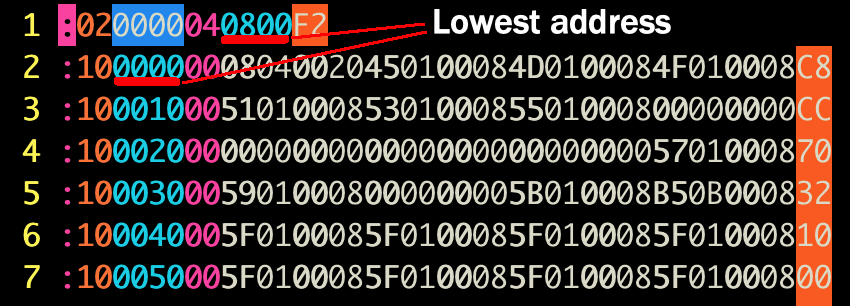
Looking at the hex file, it looks like the lowest defined address should be 0x8000000:
Here, we confirm that and write out the defined data to a separate file:
Here we use the wtf! command to write from the current location (the start of defined data @ 0x8000000) to the end of the file.
Determine the Architecture
The next thing to do is figure out the architecture. In most cases, we could just look at the markings on the chip itself, but in this case the chip was covered by an RF shield. I searched the FCC ID to find relevant FCC filings, but in this case the images weren’t particularly helpful. Here’s a cropped image showing just the processor:
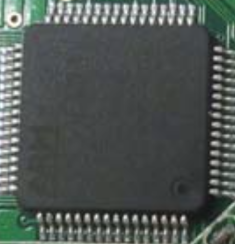
If we squint, we can read “ARM” and not much else. But that’s something! Let’s figure out some other parameters using the p=i command, which
shows the number of invalid instructions per block size. The basic process I used is to start twiddling asm values, namely
asm.bits and asm.cpu (we already know asm.arch), until we minimize the invalid instructions.
So as we can see, setting asm.bits=16 and asm.cpu=cortex seems to minimize the number of bad instructions.
Finally, if you comb through a strings dump from the image, you get this:
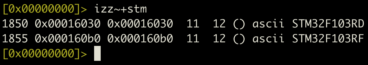
Googling those model numbers will tell us that they’re both basically the same 32-bit ARM Cortex-M3 microcontroller. So why did
the 16-bit setting work better than 32? The code is probably in Thumb mode, which r2 needs to be in 16-bit mode to handle.
Analysis: the first crack
So, just as a reminder, we’re trying to find the CAN interrupt handler. To do that, we have to find the
Interrupt Vector Table (IVT). If we check the processor documentation1, we
see that the interrupt vector table should be at 0x8000000. Here’s what the address at 0x8000000 looks like if we
interpret it as an array of 32-bit words:
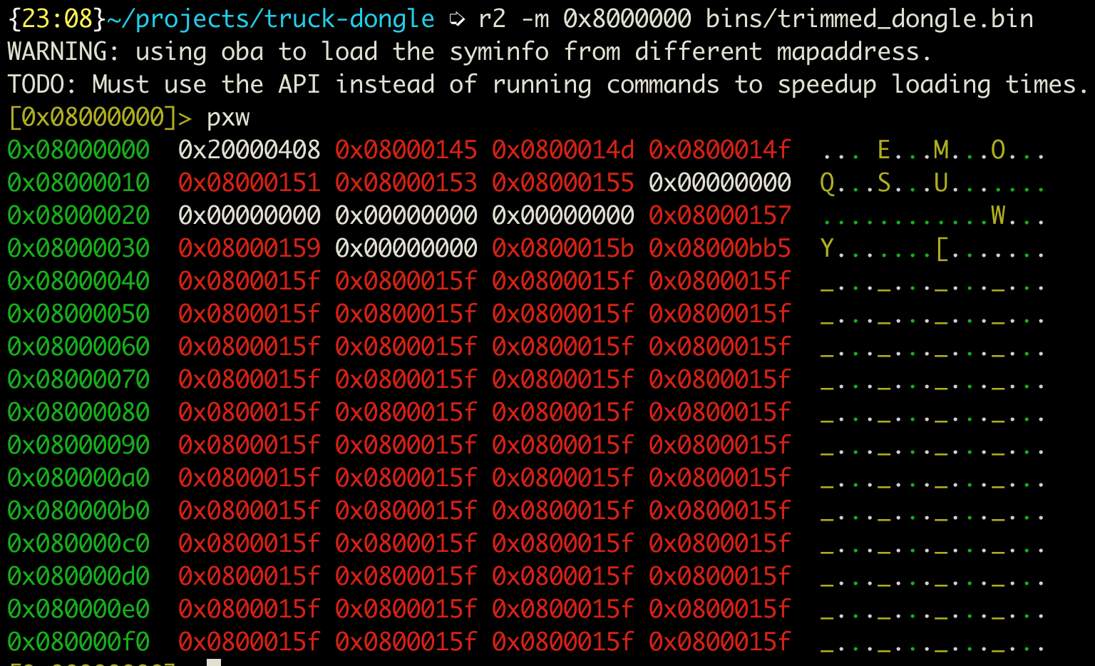
That matches what the documentation leads us to expect. The first byte is an SRAM address2, and all the rest are addresses in code flash.
They’re all odd, which means that they’re all pointers to Thumb code, so that explains
why we got the fewest invalid instructions with asm.arch set to 16.
So we’re good, right? WRONG! The CAN RX interrupt vector is at an offset of 0x90. We notice in the figure above that the pointer is the
same as all the other interrupt handlers, which is immediately discouraging. Not, however, as discouraging as when we look at the code it
points to:
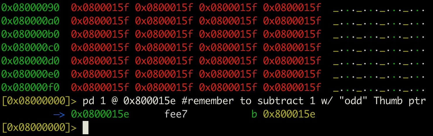
Clearly, this is not the function we want, since it’s an infinite loop. But fear not! On this platform (and many platforms), the IVT can be
moved by modifying a system register called VTOR at 0xE000ED08.
All we need to do is find crossreferences to that memory location, track writes to it, and we’re good. Right?
Let’s see how that pans out:
What happened here? There’s no xrefs here, even though we see the VTOR’s address in a few places that look like pointers.
Well, when we load the file into r2, r2 only knows about the memory addresses that we explicitly tell it about. In this case,
that’s only a couple hundred kilobytes starting at memory address 0x8000000. r2 doesn’t know anything about the address 0xE000ED08, so it
won’t track cross-references to it.
Feeding More Information to the Disassembler
So how do we tell r2 about those memory addresses? We define additional maps using the on command. We check the processor documentation1
again to find the memory map, and find that SRAM comprises a 512M block starting at 0x20000000, peripherals are another 512M block based
at 0x40000000, and Cortex peripherals (like the Vector Table Offset Register) are at 0xE0000000. The general form I used for defining a
memory block is like so:
on malloc://512M <base_addr> rw
omn <base_addr> <Name>
Typing all this in when we load the file into r2 is kind of tiresome, so I compiled all the asm directives and memory maps into a script
file. By using the -i flag when invoking r2, it will execute all of the commands after loading the file. You can find a copy of the script
file here for reference.
And there it is! Now we can do some ~static analysis~ to figure out what this thing does with CAN frames.
So now what?
To be honest, I have no concrete plans for this thing. At this point I just poke at the firmware dump during the brief periods when my
daughter is asleep. The next step may be to just take my newfound r2 skills on to other projects.
IDK though, who knows? I might adapt this thing to working with passenger vehicles instead of trucks.
Acknowledgements
Many thanks are due to @BenLGardiner, who introduced me to radare; I also cribbed some of this material from one of his workshops. Also to pancake, who gave a pretty good talk on reversing firmware with radare that got me started down the path.